Temperature Sensor Network, Part 4: Casing
This is the fourth part of my temperature sensor network series, as explained in Part1. This part goes into the design of the casing and mounting the sensors.
Casing
There have been two design for the casing of the sensor.
The first design placed the sensor inline with the rest of the dongle.
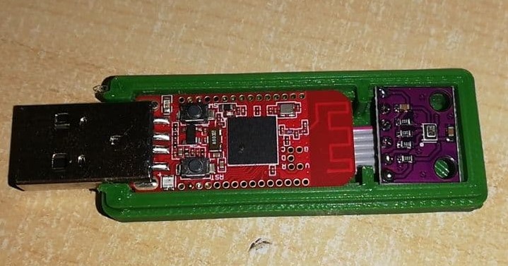 .
Sadly the flatcable running beneath the PCB antenna resulted in loss of link quality, and I received no packets from the other side of my house.
.
Sadly the flatcable running beneath the PCB antenna resulted in loss of link quality, and I received no packets from the other side of my house.
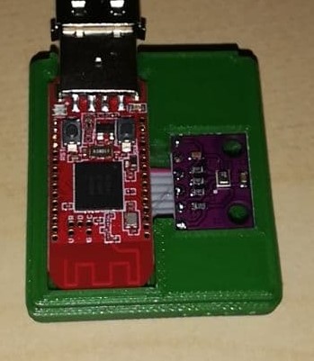
The second casing design places the sensor of to the side. It also includes more holes around the temperature sensor for more airflow and attempts to isolate the sensor from the heat of the microcontroller.
 .
.
This second casing desing appears to have better conenctivity. As the sensors connect in all rooms from my house.
The design of the sensor case and printing instruction can be found here on thingiverse.
Mounting and power
To mount the sensors I have stuck a piece of double sided tape to the back of the casing, and stuck them to the wall.
The sensors are powered using a USB-A to A cable, and a USB wall charger. Eventually I might try to battery power these sensors, but that is something for another time.
Conclusion
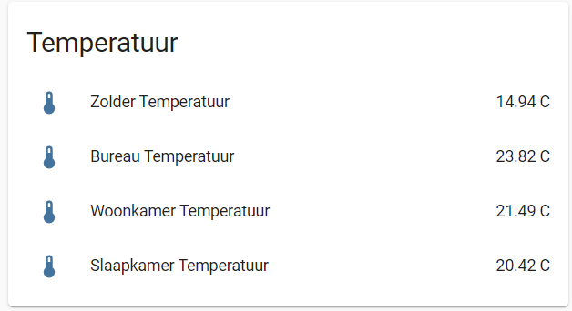
Right now I have 4 sensors in my house, which all work, they are configured with home assistant and send out data reliably.
 .
.
The bmp280 temperature reading appear to be a bit higher then those of my thermostat and that of the other sensors I have. I will have to look into this.
But overall the initial sensors have been a success.